Tuesday, April 30, 2013

1 800 Oscillator

Oscillators are ten a penny, but this one has something special. Its frequency can be adjusted over a range of 800:1, it is voltage controlled, and it switches off automatically if the control voltage is less than approximately 0.6 V. As can be seen from the chart, the characteristic curve f = f(Ue) is approximately logarithmic. If the input voltage is less than 0.7 V, T1 and T3 are cut off. The capacitor then charges via the 10-kW resistor. The combination of the capacitor, the two Schmitt triggers and T2 form the actual oscillator circuit. However, T2 cannot discharge the capacitor, because T3 is cut off.


In this state, a low level is present at A1 and a high level is present at A2. If the input voltage is increased, T3 starts conducting. This allows the capacitor to be discharged via T2, and the circuit starts to oscillate. If Ue is further increased, the capacitor receives an additional charging current via T1 and the l00-Ω resistor. That causes the oscillator frequency to increase. In situations where the duty cycle of the output signal is not important (such as when the circuit is used as a clock generator), this circuit can be used as a voltage-controlled oscillator (VCO) with a large frequency range and shutdown capability. 
Read More...

Saturday, April 13, 2013

Nokia E 51 Mic Not Working Problem Repair Solutions


Nokia E-51 Mic Not Working Problem Repair Solutions
Nokia E-51 Mic Not Working Problem Repair
Nokia E-51 Mic Not Working Problem Jumper Ways
Nokia E-51 Mic Not Working Problem Solve By Jumpers
Read More...

Remote Washing Machine Alert

It is frequently the case in this day and age that the was oncehing computing device and  tumble dryer are put in in an outbuilding  or nook of a storage. This no longer simplest makes the kitchen a so much quieter location but also leaves room for a dish was onceher and provides extra space for storing. The downside now is the best manner to inform when the used to beh cycle is finished. In dangerous climate you don’t want to make too many fruitless trips down the backyard route just to check if the was onceh cycle is finished. The author used to be confronted with this drawback when he remembered a spare wi-fi door chime he had. With a quantity of additional components and a phototransistor to passively become conscious of when the washing computing device’s ‘end’ LED comes on, the issue was once solved. 

Circuit diagram :

Remote Washing Machine Alert Circuit Diagram

C1 smoothes out any fluctuations within the LED light output (they are continuously pushed by using a multiplex signal) producing a extra secure DC voltage to enters 2 and 6 of IC1. The circuit is battery powered so the CMOS model of the familiar 555 timer is used for IC1 and IC2. The output of IC1 (pin 3) preserves IC2 reset (pin 4) held Low while there's no gentle falling on T1. When the wash cycle is finished the LED lights, inflicting T1 to conduct and the voltage on C1 starts to fall. Changing  the value of R1 will raise sensitivity if the LED will not be vivid enough. 

When the voltage on C1 falls  below 1/3 of the supply volt-age IC1 switches its output  (pin 3) High, taking out the  reset from IC2. T2 behaviors  and LED D1 is now lit, sup-plying current to cost C2.  When  the  voltage  across  C2 reaches 2/3 provide IC2  switches its output Low and  C2 is now discharged via pin  7 via R3. The discharge time  is roughly one minute before  the transistor is once more switched on. The process repeats so lengthy as gentle is falling on T1. 

Transistor T2 is a general-purpose small signal NPN kind. The open collector output is  wired directly in parallel with the bell push  (which nonetheless operates if the transistor just isn't  switched on). Ensure that transistor output is  wired to the proper bell push terminal (not the aspect related to the poor battery  terminal).
Each timer devours about 60 µA quiescent and the circuit may additionally be powered from the transmitter battery. Alternatively a 9 V battery can be substituted; it has much larger capability than the unique mini 12 V battery fitted in the bell push. Before you begin construction, take a look at the range of the wireless doorbell to make sure  the signal reaches from the was oncehing computing device to at any place the bell will be outfitted. 


Author : Götz Ringmann - Copyright : Elektor
Read More...

Inverter Overload Protector

An overload situation in an inverter may  permanently  damage  the  energy transistor array or burn off the transformer. Some of the home inverters bought in the market don't function an overload shutdown facility, whereas those incorporating this selection come with a ticket.the circuit presented here is an overload detector which shuts down the inverter  in  an  overload  situation.  

Circuit diagram:

Inverter Overload Protector With Delayed Auto Rest Circuit Diagram
 
It  hasthe following fascinating features:
  • It shuts down the inverter and additionally provides  audio-visual  indication  of  the overload condition.
  • after  shutdown,  it  robotically restarts  the  inverter  with  a  delay  of  6 2ds. accordingly, it keeps the consumer from the inconvenience  caused  due  to  manually resetting the device or operating round in darkness to reset the gadget at night.
  • It  permanently  shuts  down  the inverter  and  proceeds  to  give  audio warning,  in  case  there  are  more  than three  successive  overloads.  Under  this situation, the device has to be manually reset.(Successive overload situation point outs that the inverter  output  is  short-circuited or a heavy current is being drawn by using the connected load.)

Inverter Overload Protector With Delayed Auto Rest

The circuit uses an ammeter  (0-30a)  as  a  transducer  to  detect  overload situation.  Such  an  am-meter  is  generally  present in  almost  all  inverters.  this  ammeter  is attached between the bad provide of the battery and the inverter, as shown in Fig. 2. the voltage developed throughout this ammeter, due to the glide of current, could be very small. It is amplified by means of IC2, which is wired as a differential amplifier having a gain  of 100. IC3 (NE555) is linked as a Schmitt ‘trigger’, whose output goes low when the voltage at its pin 2 exceeds 3.3V. IC4 (again an NE555 timer) is configured as  a  monostable  multivibrator  with  a pulsewidth of 6 seconds. IC5 (CD4017) is a CMOS counter which depends the three overload  stipulations,  after  which  the  sys-tem has to be reset manually, through urgent push-to-on change S1. the  circuit  can  be  powered  from  the inverter battery. In standby situation, it devours 8-10 ma of present and round 70 mA with relay (RL1), buzzer (PZ1), and LED1 energised. 

Please note the following factors carefully:
  • Points A and B on the enter of IC2 should be connected to the corresponding points (A and B respectively) throughout the ammeter.
  • Points C and D on the relay terminals  have  to  be  related  in  series  with the  already  existing  ‘on’/‘off’  switch  leads of inverter as proven in Fig. 1. which method that some of the two leads terminated on the present  swap  has  to  be  minimize  and  the  cut ends must be connected to the pole and N/O contacts respectively of relay RL1.
  • The  ammeter  must  be  related in sequence with the bad terminal of the battery and inverter, as shown in Fig. 2.Move the wiper of preset VR1 to the extreme position which is grounded. Switch ‘on’ the inverter. For a three00W inverter, connect about 250-260W of load. Now alter VR1 slowly, unless the inverter simply go again and forths or shuts down.  repeat the step if vital. Use good-quality preset with dust cover (e.g. multiturn trimpot) for reliable operation.the circuit can also be simply and success-fully installed with minimum changes to the existing inverter. the entire parts used are low-cost and easily avail-able. the entire circuit is often assembled on a general-purpose PCB. The value of the entire circuit including relay, buzzer, and PCB does not exceed Rs one hundred.

Author : Siddharth Singh - Copyright : EFY Mag
Read More...

Friday, April 12, 2013

Intelligent Electronic Lock

This intelligent electronic lock circuit is built using transistors only. To open this electronic lock, one has to press tactile switches S1 through S4 sequentially. For deception you may annotate these switches with different numbers on the control panel/keypad. For example, if you want to use ten switches on the keypad marked ‘0’ through ‘9’, use any four arbitrary numbers out of these for switches S1 through S4, and the remaining six numbers may be annotated on the leftover six switches, which may be wired in parallel to disable switch S6 (shown in the figure). 

When four password digits in ‘0’ through ‘9’ are mixed with the remaining six digits connected across disable switch terminals, energisation of relay RL1 by unauthorized person is prevented.For authorized persons, a 4-digit password number is easy to remember. To energies relay RL1, one has to press switches S1 through S4 sequentially within six seconds, making sure that each of the switch is kept depressed for a duration of 0.75 second to 1.25 seconds. The relay will not operate if ‘on’ time duration of each tactile switch (S1 through S4) is less than 0.75 second or more than 1.25 seconds.

This would amount to rejection of the code. A special feature of this circuit is that pressing of any switch wired across disable switch (S6) will lead to disabling of the whole electronic lock circuit for about one minute. Even if one enters the correct 4-digit password number within one minute after a ‘disable’ operation, relay RL1 won’t get energized. So if any unauthorized person keeps trying different permutations of numbers in quick successions for energisation of relay RL1, he is not likely to succeed. To that extent, this electronic lock circuit is fool-proof. This electronic lock circuit comprises disabling, sequential switching, and relay latch-up sections. The disabling section comprises zener diode ZD5 and transistors T1 and T2. Its function is to cut off positive supply to sequential switching and relay latch-up sections for one minute when disable switch S6 (or any other switch shunted across its terminal) is momentarily pressed.
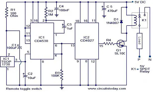
Circuit diagram :
Intelligent Electronic Lock -Circuit-Diagram

Intelligent Electronic Lock Circuit Diagram

During idle state, capacitor C1 is in discharged condition and the voltage across it is less than 4.7 volts. Thus zener diode ZD5 and transistor T1 are in non-conduction state. As a result, the collector voltage of transistor T1 is sufficiently high to forward bias transistor T2. Consequently, +12V is extended to sequential switching and relay latch-up sections. When disable switch is momentarily depressed, capacitor C1 charges up through resistor R1 and the voltage available across C1 becomes greater than 4.7 volts. Thus zener diode ZD5 and transistor T1 start conducting and the collector voltage of transistor T1 is pulled low. As a result, transistor T2 stops conducting and thus cuts off positive supply voltage to sequential switching and relay latch-up sections. Thereafter, capacitor C1 starts discharging slowly through zener diode D1 and transistor T1. It takes approximately one minute to discharge to a sufficiently low level to cut-off transistor T1, and switch on transistor T2, for resuming supply to sequential switching and relay latch-up sections; and until then the circuit does not accept any code.

The sequential switching section comprises transistors T3 through T5, zener diodes ZD1 through ZD3, tactile switches S1 through S4, and timing capacitors C2 through C4. In this three-stage electronic switch, the three transistors are connected in series to extend positive voltage available at the emitter of transistor T2 to the relay latch-up circuit for energising relay RL1.  When tactile switches S1 through S3 are activated, timing capacitors C2, C3, and C4 are charged through resistors R3, R5, and R7, respectively. Timing capacitor C2 is discharged through resistor R4, zener diode ZD1, and transistor T3; timing capacitor C3 through resistor R6, zener diode ZD2, and transistor T4; and timing capacitor C4 through zener diode ZD3 and transistor T5 only. The individual timing capacitors are chosen in such a way that the time taken to discharge capacitor C2 below 4.7 volts is 6 seconds, 3 seconds for C3, and 1.5 seconds for C4. Thus while activating tactile switches S1 through S3 sequentially, transistor T3 will be in conduction for 6 seconds, transistor T4 for 3 seconds, and transistor T5 for 1.5 seconds.

The positive voltage from the emitter of transistor T2 is extended to tactile switch S4 only for 1.5 seconds. Thus one has to activate S4 tactile switch within 1.5 seconds to energise relay RL1. The minimum time required to keep switch S4 depressed is around 1 second. For sequential switching transistors T3 through T5, the minimum time for which the corresponding switches (S1 through S3) are to be kept depressed is 0.75 seconds to 1.25 seconds. If one operates these switches for less than 0.75 seconds, timing capacitors C2 through C4 may not get charged sufficiently. As a consequence, these capacitors will discharge earlier and any one of transistors T3 through T5 may fail to conduct before activating tactile switch S4.  Thus sequential switching of the three transistors will not be achieved and hence it will not be possible to energise relay RL1 in such a situation. A similar situation arises if one keeps each of the mentioned tactile switches de-pressed for more than 1.5 seconds.

When the total time taken to activate switches S1 through S4 is greater than six seconds, transistor T3 stops conducting due to time lapse. Sequential switching is thus not achieved and it is not possible to energise relay RL1. The latch-up relay circuit is built around transistors T6 through T8, zener diode ZD4, and capacitor C5. In idle state, with relay RL1 in de-energised condition, capacitor C5 is in discharged condition and zener diode ZD4 and transistors T7, T8, and T6 in non-conduction state. However, on correct operation of sequential switches S1 through S4, capacitor C5 is charged through resistor R9 and the voltage across it rises above 4.7 volts. Now zener diode ZD4 as well as transistors T7, T8, and T6 start conducting and relay RL1 is energised. Due to conduction of transistor T6, capacitor C5 remains in charged condition and the relay is in continuously energised condition. Now if you activate reset switch S5 momentarily, capacitor C5 is immediately discharged through resistor R8 and the voltage across it falls below 4.7 volts. Thus zener diode ZD4 and transistors T7, T8, and T6 stop conducting again and relay RL1 de-energises.

Source :http://www.ecircuitslab.com/2011/10/intelligent-electronic-lock.html
Read More...

Probing Solar Panel Design Systems

Current drawbacks of utilizing solar energy are high initial costs and the inconvenience of high maintenance. Although the use of solar energy has been steadily growing, it is only 0.08 percent of the energy-producing market within the United States.1One of the growing areas in solar research has been the mounting brackets of solar arrays. The goal of this design project is to develop innovative methods for producing an inexpensive mounting system to reduce initial costs of a photovoltaic solar grid. Limited engineering research in this area has kept these panels retailing at the average cost of $600 per panel, while the mounting system costs per panel are over $100. Thus, this article will discuss possible cost-effective solutions for mounting systems. In addition, experimental methods for testing the panels will be suggested. has dictated the creation of the three subsequent designs. MIT facilities recently received a grant to install solar panels on campus.2The supplier of solar panels uses various panel sizes that are not compatible with the Modulardesign. It would therefore be necessary to have shorter or longer slats depending on the specific size of the panel as there is not one industry standard. This issue spurred the idea of having a configuration.

Get from here to download Probing Solar Panel Design Systems
Read More...

Modular Jack Wiring Jack Pins Numbered

Phone Jack Wiring Diagram on Pin Modular Jack Wiring Jack Pins Are Numbered Looking
Pin Modular Jack Wiring Jack Pins Are Numbered Looking.


Phone Jack Wiring Diagram on Terminal  The Steps To Wire A Jack As Shown Above Are As Follows
Terminal The Steps To Wire A Jack As Shown Above Are As Follows.


Phone Jack Wiring Diagram on Phone Might Damage The Network Card When The Phone Rings The Wiring
Phone Might Damage The Network Card When The Phone Rings The Wiring.


Phone Jack Wiring Diagram on Typical Phone Jack Wiring
Typical Phone Jack Wiring.


Phone Jack Wiring Diagram on Triple Contact Plug Or Trs Plug Or Trs Connector Has Three
Triple Contact Plug Or Trs Plug Or Trs Connector Has Three.


Phone Jack Wiring Diagram on Telephone Jack Wiring Dsc09942 Jpg
Telephone Jack Wiring Dsc09942 Jpg.


Phone Jack Wiring Diagram on Wires Inside Most Phone Jacks Are Usually Solid Colored Not
Wires Inside Most Phone Jacks Are Usually Solid Colored Not.


Phone Jack Wiring Diagram on The Following Is A Diagram Of How A Jack Works
The Following Is A Diagram Of How A Jack Works.


Phone Jack Wiring Diagram on We Use A De9f To Rj45 Adapter Part No 01910 From Www Pccables Com To
We Use A De9f To Rj45 Adapter Part No 01910 From Www Pccables Com To.


Phone Jack Wiring Diagram on Zen Vision  M Video Cable   Other 4 Pole 3 5mm Pinouts   Anything But
Zen Vision M Video Cable Other 4 Pole 3 5mm Pinouts Anything But.


Read More...

Vocal Adaptor for Bass Guitar Amp

These days, music is a major hobby for the young and not-so-young. Lots of people enjoy making music, and more and  more dream of showing off their talents on  stage. But one of the major problems often encountered is the cost of musical equipment. How many amateur music groups sing through an amp borrowed from a guitarist or bass player?

This is where the technical problems arise not in terms of the .25” (6.3 mm)  jack, but in terms of the sound quality (the words are barely understandable) and volume (the amp seems to produce fewer decibels than for a guitar). What’s more, unpredictable feedback may cause damage to the speakers and is very unpleasant on the ear. This cheap little easy-to-build project can help solve these technical problems.

Vocal Adaptor for Bass Guitar Amp Circuit diagram :

Vocal Adaptor for Bass Guitar Amp-Circuit Diagram

A guitar (or bass guitar) amplifier is designed first and foremost to reproduce the sound of the guitar or bass as faithfully as possible. The frequency response of the amp doesn’t need to be as wide or as flat as in hi-fi (particularly at the  high end), and so this sort of amplifier won’t  permit faithful reproduction of the voice. If you build an adaptor to compensate for the amp’s limited frequency response by amplifying in advance the frequencies that are then attenuated by the amp, it’s possible to improve the quality of the vocal sound. That’s just what this circuit attempts to do.

The adaptor is built around the TL072CN low-noise dual FET op-amp, which offers good value for money. The NE5532 can be used with almost the same sound quality, but at (slightly) higher cost. The circuit breaks  down into two stages. The first stage is used to match the input impedance and amplify the microphone signal. For a small 15 W guitar or bass amplifier, the achievable gain is about 100 (gain = P1/R1). For more powerful amplifiers, the gain can be reduced to  around 50 by adjusting P1. The second stage  amplifies the band of frequencies (adjustable using  P2 and P3) that are attenuated by the guitar amp, so as to be able to reproduce the (lead) singer ’s voice as clearly, distinctly, and  accurately as possible. To refine the adaptor and tailor it to your amplifier and speaker, don’t be afraid to  experiment with the component values and the type of capacitors.

The circuit can readily be powered using a 9 V battery, thanks to the voltage  divider R4/R5 which converts it into a symmetrical  ±4.5 V supply.

Author :Jérémie Hinterreiter - Copyright : Elektor

Read More...

The parts of the Speaker

Basket (frame)
Made of a metal plate that will support all parts of the speaker where the speaker of the other speakers can be attached to the intact 

Magnet
Here is used to generate a magnetic field of permanent magnets to be used to drive the voice coil, so as to produce sound.

speaker parts, parts of loudspeaker, speaker parts, how to roll the speaker coil, the image - the speaker
Parts of speaker
Voice Coil
Voice Coil is an important part of a speaker. Voice coil consists of Robbin (where rolled coil) and coil (the coil BWR - Brass Wire Rope), Coil is going to move in accordance with the signal diterirna.

Spieder or Damper
Spider or suspension dampers are used to speakers that serve to dampen the vibrations of the voice coil, so the voice coil can move freely.

Cone Paper
Paper Cone is part of the suspension of the speaker who serves simultaneously as an amplifier of vibration caused by the voice coil so it can form a clear voice signal received from the speakers.

Dust Cap
Dust Cap serves to channel sound vibration with paper cone and protect the inside of the speaker (where the air gap voice coil moves) from the dust and dirt.
see also : Subwoofer Amplifier
Read More...

Build A Synchronous Clock

The quartz clocks which have dominated time-keeping for the past 20 years or so have one problem: their errors, although slight, are cumulative. After running for several months the errors can be significant. Sometimes you can correct these if you can slightly tweak the crystal frequency but otherwise you are forced to reset the clock at regular intervals. By contrast, mains-powered synchronous clocks are kept accurate by the 50Hz mains distribution system and they are very reliable, except of course, when a blackout occurs. This circuit converts a quartz clock to synchronous mains operation, so that you can have at least one clock in your home which shows the time. First, you need to obtain a quartz clock movement and disassemble it down to the PC board. For instructions on how to do this, see the article on a "Fast Clock For Railway Modellers" in the December 1996 issue of SILICON CHIP. Then isolate the two wires to the clock coil and solder two light duty insulated hookup wires to them (eg, two strands of rainbow cable). Drill a small hole in the clock case and pass the wires through them. Then reassemble the clock case.

Circuit diagram:

building_a_synchronous_clock circuit

A Synchronous Clock Circuit Diagram

To test the movement, touch the wires to the terminals of an AA cell, then reverse the wires and touch the cell terminals again. The clock second hand should advance on each connection. The circuit is driven by a low voltage AC plug pack. Its AC output is fed to two bridge rectifiers: BR1 provides the DC supply while BR2 provides positive-going pulses at 100Hz to IC1a, a 4093 NAND Schmitt trigger. IC1a squares up the 100Hz pulses and feeds them to the clock input of the cascaded 4017 decade counters. The output at pin 12 of IC3 is 1Hz. This is fed to IC4, a 4013 D-type flipflop, which is connected so that its two outputs at pins 12 & 13 each go positive for one second at a time. As these pulses are too long to drive the clock movement directly, the outputs are each fed to 4093 NAND gates IC1b & IC1c where they are gated with the pin 3 signal to IC4. This results in short pulses from pins 3 & 10 of IC1 which drives the clock via limiting resistor R1. The value of R1 should be selected on test, allowing just enough current to reliably drive the clock movement.
Author: A. J. Lowe - Copyright: Silicon Chip

Source: 
Read More...

Thursday, April 11, 2013

25W Audio Power Amplifier Rise

This audio power amplifier project is based on LM1875 amplifier module from National Semiconductor. It can deliver up to 30W of power using an 8 ohm load & dual 30V DC power supplies. It is designed to operate with maximum outside parts with current limit & thermal shutdown protection features . Other features include high gain, quick slew rate, wide power supply range, giant output voltage swing & high current capability.

Summary of the audio amply-fire features:

  • Low distortion: 0.015%, 1 kHz, 20 W
  • Wide power bandwidth: 70 kHz
  • Wide supply range 16V-60V
  • Up to 30 watts output power
  • Internal output protection diodes
  • Protection for AC & DC short circuits to ground
  • 94 dB ripple rejection
  • Plastic power package TO-220
25V Power Supply

The schematic below shows how the +25V DC & -25V DC are obtained. In order to provide power supply for two stereo amplifiers, a power transformer rating of 80VA with 240V/36V middle tapped secondary winding is used. The secondary output of the transformer is rectified by using 1N5401 diodes together with four electrolytic capacitors to smoother the ripple voltage. A fuse & a varistor are connected at the primary input to protect the circuit against power surge.


Audio Amplifier Module

The +25V & -25V DC power supply are connected to the audio amplifier module through a 2A fuse with the peripheral devices shown in the schematic below. The audio input signal to be amplified is coupled to pin one of LM1875 through the resistor R1 and electrolytic capacitor E5.

The output signal at pin four of LM1875 can be used to directly drive a 8 ohm loudspeaker. Resistor R6 and capacitor C5 prevent-the capacitance developed at the long speaker leads from driving the amplifier in to High Frequency Oscillation.

A heat-sink with a thermal resistance rating of one.4 Cecilius/Watt or better must be used or else the amplifier module will-be cut-off from operation due to the heat that will build up in the coursework of the operation of the amplifier. Take note that the heat sink tab on the IC module is internally connected to the -25V power supply hence it must be isolated from the heat sink by the use of an insulating washer. If this is not done, the negative rail will be shorted to ground.


Read More...

Design a Subtractor


A basic differential amplifier can be used as a sub-tractor. We can get
the difference of two input voltages in the output of op-amp as output
voltage. The circuit diagram of a basic differential amplifier is drawn below.


         This is a linear bilateral network. So, applying super position theorem, we can find the output voltage equation.
Let, assume that only Va is applied and Vb is short.
Read More...

Alternator Wiring

Alternator Wiring on Marine Alternator Diagram Mando Alternator Wire Marine Alternator
Marine Alternator Diagram Mando Alternator Wire Marine Alternator.


Alternator Wiring on Alternator Wiring Question   Page 1   450965
Alternator Wiring Question Page 1 450965.


Alternator Wiring on Alternator Regulator Troubleshooting
Alternator Regulator Troubleshooting.


Alternator Wiring on Please Note The Fuse Wire Connected To The Starter Solenoid And Not
Please Note The Fuse Wire Connected To The Starter Solenoid And Not.


Alternator Wiring on Do This An Nothing Else
Do This An Nothing Else.


Alternator Wiring on 68 Charging At 14 8v And Acid Leaking From The Battery   Vintage
68 Charging At 14 8v And Acid Leaking From The Battery Vintage.


Alternator Wiring on Ls1 Alternator Wiring
Ls1 Alternator Wiring.


Alternator Wiring on Alternator Bracket For The Top Mounting About   15 On Line The Wiring
Alternator Bracket For The Top Mounting About 15 On Line The Wiring.


Alternator Wiring on 12v Marine Tachometer Diesel Alternator Wiring Instruction Jpg
12v Marine Tachometer Diesel Alternator Wiring Instruction Jpg.


Alternator Wiring on 1994 Saturn Sl2 Problem New Alternator Bad Electrical 4 Cyl Front
1994 Saturn Sl2 Problem New Alternator Bad Electrical 4 Cyl Front.


Read More...

First Order Band Pass Filter


          Application of first order band pass filter to find out the output voltage gain magnitude of specific frequency. A specific range of frequency can pass through the amplifier which has a specific bandwidth of this band pass filter.

A
band pass filter is a frequency selector. It allows one to select or
pass only one particular band of frequencies from all other frequencies
that may be present in a circuit. This type of filter has a maximum gain
at a resonant frequency.


A
band pass filter is the combination of high pass and low pass filter
combination. It has a pass band between two cut off frequency fH and fL such that fH > fL. Any input frequency outside this pass band is attenuated. There are two types of band pass filters wide band pass and narrow band pass. If the quality factor Q < 10
and Q > 10 then it would be wide band pass and narrow band pass filter.

          The relationship between Q, the 3-dB bandwidth and the center frequency fc is given by,


According to Figure 01 of band pass filter circuit, there are two
sections. One is first order high pass section and other is low pass
section.

 For first order high pass section the output voltage equation is,
For first order low pass section the output voltage equation is,

Putting the value of first order high pass section output voltage  from equation (1),


So the final voltage equation of first order band pass filter is,
        
         The voltage gain magnitude of the band pass filter is equal to the product of the voltage gain magnitudes of the high pass and low pass filters.


Therefore the equation (2) is,
Where,  = Total band pass gain
f = frequency of the input signal (Hz)
 = low cut off frequency (Hz)
= high cut off frequency (Hz)

The above first order low pass band width filter was designed by taking following precautions,
a.       
 Limited magnitude of input voltage was applied at the input, so that the op-amp must not be driven to saturation.

b.                 Only selected frequency can pass through the filter.

c.                         Overall gain of the first order band pass filter is the multiplication of  high pass filter gain and low pass filter gain.
Read More...

Remote toggle switch circuit

The only difference is in the approach. This
circuit is designed by using another method. Using this circuit you can
toggle any electrical appliance between ON and OFF states by using
your TV remote. The only requirement is that your TV remote should be
operating in the 38 KHz.
 The IC1 (TSOP 1738)
is used to receive the infrared signals from the remote. When no IR
signal from remote is falling on IC1, its output will be high. When the
IR signal from the remote falls on the IC1, its output goes low. This
triggers the IC2 which is wired as a monostable multivibrator.The
output of the IC2 (pin6) goes high for a time of 1S (set by the values
of R2 and C3.This triggers the flip flop (IC2) and its Q output (pin
15) goes high. This switches on the transistor, which activates the
relay and the appliance connected via relay is switched ON. For the
next press of remote the IC1 will be again triggered which in turn
makes the IC2 to toggle its output to low state. The load will be
switched OFF. This cycle continues for each press of the remote. The
pin 6 and pin 4 of IC1 are shorted to avoid false triggering.The diode
D1 can be used as a freewheeling  diode.
Circuit diagram with Parts list.
remote-toggle-switch.jpg
Notes.
  • Assemble the circuit on a good quality PCB or common board.
  • The circuit can be powered from  a 5V DC regulated power supply.
  • The capacitors must be rated 15 V.
  • The IC1&IC2 must be mounted on holders.
  • The
    current capacity  of relay determines the load circuit can switch.Use a
    high amperage(`10A or above) relay for driving large loads like
    motor,heater etc.
Read More...

How to repair Nokia 5610 keypad fail problem

For nokia 5610 keypad can not function normally

1. Check and clean keypad and doomsheet first
2. If the problem not solved, check flex cable, replace if needed
3. If the problem still not solved , check asip emif keypad and replace if needed.
4. If the problem still not solved, track circuit for broken line.


Read More...

Wednesday, April 10, 2013

Heart Rate Monitor

Strictly speaking, this simple circuit shouldnt work! How could anyone expect an ordinary light dependent resistor photo cell to see through a fingertip in natural daylight and detect the change in blood flow as the heart pulsates? The secret is a high gain circuit, based on a dual op amp IC which can be either the low power LM358 or the JFET TL072. The LDR is connected in series across the 9V battery supply via a 100kO resistor (R1) and the minute signal caused by the blood pulsing under the skin is fed to the non-inverting (+) input, pin 3, of IC1a via a 0.µF capacitor.

Pin 3 is biased by a high impedance voltage divider consisting of two 3.3MO resistors. The feedback resistors to pin 2 set the gain to 11 times. The output of IC1a is fed via a 0.47µF capacitor and 220kO resistor to IC1b. This is configured as an inverting op amp with a gain of 45 so that the total circuit gain is about 500. The output of IC1b is used to drive an analog meter which may be a multimeter set to the 10V DC range or any panel meter in series with a resistor to limit the current to less than its full-scale deflection. The prototype used an old VU meter with a 47kO resistor fitted in series.

Circuit diagram:
heart-rate-monitor circuit diagram
Heart Rate Monitor Circuit Diagram

Note that the unit was designed to use the Dick Smith Electronics light dependent resistor (Z-4801). Other LDRs may require a change in the value of resistor R1. A light source such as a high brightness LED is not required. All that is needed is a reasonably well-lit room, preferably natural daylight, to produce a healthy swing of the needle. Only when the hands are very cold does it make it a little more difficult to accurately count the pulses. To check your heart rate, carefully position your thumb or finger over the LDR and count the meter fluctuations for a period of 15 seconds. Then multiply the result by four to obtain your pulse rate. The circuit can not be used if you are walking or running, etc.
 
 
Streampowers
Read More...

Garage Timer Circuit Diagram

The circuit described here is a testament to the ingenuity of two young designers from  a specialist  technical secondary school. The ‘garage timer’ began as a school electronics project and has now made it all the way to publication in our Summer Circuits special issue of Elektor Electronics. The circuit demonstrates that the application possibilities for the 555 and 556 timer ICs are by no means exhausted. So what exactly is a ‘garage timer’?
When the light switch in the garage is pressed, the light in the garage comes on for two minutes. Also, one minute and forty-five  seconds  after  the  switch is pressed, the outside light also comes on for a period of one minute. The timer circuit is thus really two separate timers. Although the circuit for the interior light timer is relatively straightforward, the exterior light timer has to deal with two time intervals. First the 105 second period must expire; then the exterior light is switched on, and after a further 60 seconds the light is turned off. To realise this sequence of events, a type 556 dual timer device, a derivative of the 555, is used.
Circuit diagram:
Garage Timer Circuit Diagram
The first of the two timers triggers the second after a period of 105 seconds. The second timer is then active for 60 seconds,and it is this timer that controls the exterior light. The interior light timer is triggered at the same moment as the dual timer. In this case a simple 555 suffices, with an output active for just two minutes from the time when the switch is pressed. Push-button S1 takes over the role of the wall-mounted light switch, while S2 is provided to allow power to be removed from the whole circuit if necessary. The circuit could be used in any application where a process must be run for a set period after a certain delay has expired.
For the school project the two garage lights are simulated using two LEDs. This will present no obstacle to experienced hobbyists, who will be able to extend the circuit, for example using relays, to control proper lightbulbs. The principles of operation of type 555 and 556 timers have been described in detail previously in Elektor Electronics, but we shall say a few words about the functions of Ic1a, IC1b and IC2.
When S1 is pressed (assuming S2 is closed!) the trigger inputs of both IC1a and IC2 are shorted to ground, and so the voltage at these inputs (pins 6 and 2 respectively) falls to 0 V.  The outputs of IC1a and IC2 then go to logic 1, and D2 (the interior light) illuminates. Capacitors  C1  and  C8  now  start  to charge via P1 and R2, and R8 and P3 respectively. When the voltage on C8 reaches two thirds of the supply voltage, which happens after 120 seconds, the output of IC2, which is connected as a monostable multivibrator, goes low. D2 then goes out. This accounts for the interior light function.
Likewise, 105 seconds after S1 is closed, the voltage on C1 reaches two thirds of the supply voltage and the output of Ic1a goes low. Thanks to C4, the trigger input of IC1b now receives a brief pulse to ground, exactly as IC1a was triggered by S1. The second monostable, formed by IC1b, is thus triggered. Its pulse duration is set at one minute, determined by C5, R5 and P2. D1 thus lights for one minute. Potentiometers P1, P2 and P3 allow the various time intervals to be adjusted to a certain extent.
If considerably shorter or longer times are wanted, suitable changes should be made to the values of C1, C5 and C8. The period of the monostable is given by the formula T = 1.1 RC where T is the period in seconds, R the total resistance in ohms, and C the capacitance in farads.
Author :Daniel Lomitzky and Mikolajczak Tyrone  Copyright :Electro
Read More...

Morning Alarm Circuit Diagram Using LDR


Description

          Circuit showing a morning alarm.Here we have used a switching transistor.When the sun rise up ldr is low resistance so the ldr is conduct and a positive volt coming to the base of the Q1 there for the transistor will switch.This time  the buzzer is ON . Adjust the preset control the intensity of light.Manually cut off the power.Are you interested please comment and join this site


Component Required

                Resistor  4.7k preset  , LDR

                Transistor   BC 548

                Buzzer


Source by : http://www.electronics-circuits.in/2012/01/morning-alarm.html


Read More...

Security Alarm

Thwart any attempt of burglary in your house using this alarm circuit. When someone opens the door of your room, it sounds an alarm intermittently and flashes light as well. The circuit can also be used as an audio/visual alarm in case of fire or other emergency by momentarily pressing switch S3.

The circuit (refer Fig.1) is built around transformer X1, a standard bar magnet, reed switch S2, timer IC NE555 (IC1), opto-coupler IC MOC3020 (IC2), TRIAC BT136 and a few discrete components. Timer IC1 is wired as an astable multi-vibrator whose reset pin 4 is controlled by the reed switch. The reed switch fitted in the door frame acts as the sensor. A magnet is fixed on the door panel close to the reed switch.

Fig.1: Simple Security Alarm Circuit Diagram :

Security-alarm-circuit-Daigram

The reed switch consists of a pair of contacts on ferrous metal sealed in a glass envelope. The contacts may be normally-open (which close when a magnetic field is present) or normally closed type (which open when a magnetic field is applied). A normally open- type reed switch is used here.

When the door is closed, reed switch S2 is in open state. When the door is opened, the bar magnet moves away from reed switch S2. As a result, reset pin 4 of IC NE555 goes high. The high output at pin 3 of IC1 enables IC2. Pin 4 of IC2 is connected to the gate of TRIAC1. When the door is opened, bulb B1 flashes and the bell sounds (provided switch S4 is closed) indicating that the door has been opened. Flashing of the bulb and the alarm continue until the door is closed.

Assemble the circuit on a general purpose PCB and enclose in a suitable cabinet. Connect the call bell at the back side and the bulb at the front side of the cabinet. Install the unit on the door of the room as shown in Fig.2.

Fig.2: Reed Switch Fitting in Door :

Reed-switch-fitting-in-door-d

The circuit is powered by mains supply.

Source : http://www.ecircuitslab.com/2012/09/simple-security-alarm.html
Read More...

500W Low Cost 12V to 220V Inverter

Note :This Circuit is using high voltage that is lethal. Please take appropriate precautions
Using this circuit you can convert the 12V dc in to the 220V Ac. In this circuit 4047 is use to generate the square wave of 50hz and amplify the current and then amplify the voltage by using the step transformer. How to calculate transformer rating
500w_220v_inverter_corrected
The basic formula is P=VI and between input output of the transformer we have Power input = Power output
For example if we want a 220W output at 220V then we need 1A at the output. Then at the input we must have at least 18.3V at 12V because: 12V*18.3 = 220v*1
So you have to wind the step up transformer 12v to 220v but input winding must be capable to bear 20A.

Source :  http://www.ecircuitslab.com/2011/08/500w-low-cost-12v-to-220v-inverter.html
Read More...