Friday, August 16, 2013
Wiring Diagram

Pin S Type Caravan Wiring Uk Trailer Parts.
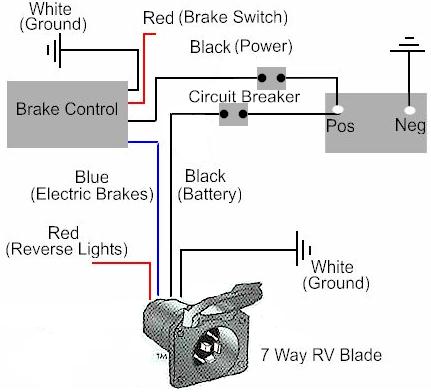
Electric Trailer Brake Controller Wiring.

2004 Gmc 2500hd Trailer Wiring Diagram Circuit Schematic.

12s Wiring Diagram.

Trailer Wiring Diagram Light Plug Brakes Hitch 4 Pin Way Wire Brake.

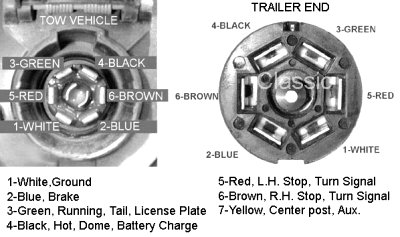
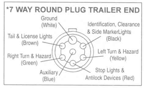
Way 7 Pole Rv Travel Trailer Connector Wiring Color Code.
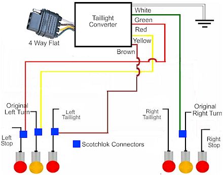
How To Install A Trailer Light Taillight Converter In Your Towing.

Wiring For 13 Pin Euro Plugs Sockets For Trailers Caravans Uk.

Trailer Wiring Diagrams Etrailer Com.

Trailer Wiring Basics For Towing.
Wednesday, August 14, 2013
Build a Universal Active Filter Circuit Diagram
The Universal Active Filter Circuit Diagram as shown gives the bandpass operation the transfer function calculated from FBP(s) = where = 1 + s/Qo>0 + s2/w02. The cut-off frequency, 0, and the Q-factor are given by 0 = g/C and Q = gR/2 where g is the trans conductance at room temperature. Interchanging the capacitor C with the resistor R at the input of the circuit high-pass operation is obtained. A low-pass filter is obtained by applying two parallel connections ctf R and C as shown in Fig. 2. The low-pass operation may be much improved with the circuit as given in Fig. 3. Here the gain and Q may be set up separately with respect to the cut-off frequency according to the equations Q = 1/fB = 1 + R2/R!, A = Q2 and 0 = g ffi/C.
Build a Universal Active Filter Circuit Diagram

Monday, August 12, 2013
1W BTL Audio Amplifier circuit and explanation
The TDA8581(T) from Philips Semiconductors is a 1-watt Bridge Tied Load (BTL) audio power amplifier capable of delivering 1 watt output power into an 8-Wload at THD (total harmonic distortion) of 10% and using a 5V power supply. The schematic shown here combines the functional diagram of the TDA8551 with its typical application circuit. The gain of the amplifier can be set by the digital volume control input. At the highest volume setting, the gain is 20 dB. Using the MODE pin the device can be switched to one of three modes: standby (MODE level between Vp and Vp–0.5 V), muted (MODE level between 1 V and Vp–1.4 V) or normal (MODE level less than 0.5 V). The TDA8551 is protected by an internal thermal shutdown protection mechanism. The total voltage loss for both MOS transistors in the complementary output stage is less than 1 V.
Circuit diagram:
Using a 5-V supply and an 8-W loudspeaker, an output power of 1 watt can be delivered. The volume control has an attenuation range of between 0 dB and 80 dB in 64 steps set by the 3-state level at the UP/DOWN pin: floating: volume remains unchanged; negative pulses: decrease volume; positive pulses: increase volume Each pulse at he Up/DOWN pin causes a change in gain of 80/64 = 1.25 dB (typical value). When the supply voltage is first connected, the attenuator is set to 40 dB (low volume), so the gain of the total amplifier is then –20 dB. Some positive pulses have to be applied to the UP/DOWN pin to achieve listening volume. The graph shows the THD as a function of output power. The maximum quiescent current consumption of the amplifier is specified at 10 mA, to which should be added the current resulting from the output offset voltage divided by the load impedance.
Circuit diagram:
1 Watt BTL Audio Amplifier Circuit Diagram
Using a 5-V supply and an 8-W loudspeaker, an output power of 1 watt can be delivered. The volume control has an attenuation range of between 0 dB and 80 dB in 64 steps set by the 3-state level at the UP/DOWN pin: floating: volume remains unchanged; negative pulses: decrease volume; positive pulses: increase volume Each pulse at he Up/DOWN pin causes a change in gain of 80/64 = 1.25 dB (typical value). When the supply voltage is first connected, the attenuator is set to 40 dB (low volume), so the gain of the total amplifier is then –20 dB. Some positive pulses have to be applied to the UP/DOWN pin to achieve listening volume. The graph shows the THD as a function of output power. The maximum quiescent current consumption of the amplifier is specified at 10 mA, to which should be added the current resulting from the output offset voltage divided by the load impedance.
Saturday, August 10, 2013
Flugzeugepiper 32rt Lance

Flugzeuge De Piper Pa 32rt 300 Lance Ii.

Flugzeuge De Piper Pa 46 350p Malibu Mirage.

Flugzeuge De Pa 28 181 Archer Ii.

Origin United States Of America Manufacturer Piper Aircraft First.

Flugzeuge De Piper Pa 42 720 Cheyenne Iiia.

Piper Pa 28 181 Flugzeug Zu Verkaufen Ad Idno 100580 Aircraft24.

Civil Fabricante Piper Aircraft Introducido 1960 Estado En Servicio N.

G Lker Traum Vom Fliegen Beautyshots Piper L 4 Grasshopper.

Flugzeuge De Piper Pa 28 161 Cadet Ph Vfc.

Flugzeuge De Piper P28 T Flughafen Tonder D Nemark.
Thursday, August 8, 2013
TDA7360 stereo circuit schematic

TDA7360 stereo circuit schematic
Above circuit diagram shows this TDA7360 stereo test and application circuit schematic.
Value recommendation of each external components of this circuit can be
described as follows: 1. C1 for input decoupling (CH1) is 0.22 uF
2. C2 for input decoupling (CH2)3is 0.22 uF
3. C3 for supply voltage rejection filtering capacitor.
4. C4 for 22uF standby ON/OFF delay
5. C5 minimal 220uF for standby-pass
6. 100 nF for C6 with its ability to supply by-pass
7. 2200 uF for the C7 of Output decoupling CH2
Tuesday, August 6, 2013
Trailer Wiring Electrical Connections Boat

Trailer Light Wiring Typical Trailer Light Wiring Diagram.

Trailer Wiring Electrical Connections Are Used On Car Boat And.

Typical 7 Way Trailer Wiring Diagram Circuit Schematic.

Trailer Wiring Diagrams Johnson Trailer Sales Colfax Wisconsin.

Way Trailer Wiring Diagram And Connectors Pinout Circuit Schematic.

Post It But I Ll Try To Diagram It Here.

Pj Trailers Plug Diagram.
Troubleshooting Trailer Wiring.
Trailer Wiring Diagrams Johnson Trailer Sales Colfax Wisconsin.

This Allows You To Connect Up The Wiring To Tow A Caravan Or Trailer.
Sunday, August 4, 2013
Running LED with 4017
Running LED with 4017 complete with PCB layout. The series of 8 LED current is the basis for creating an 8-point LED. Slightly different from the running LED with IC 4017 (decade counter), 8 running this led is lit in sequence, but that has been previously flame does not die when the led is lit afterwards. 8 led to death after led to the fire-8. Meanwhile in the running LED (decade counter), the system LED lights like "point", there is only one LED that flashes between the tenth led.

The main component is the IC 74LS164 (SHIFT REGISTER), with its timer is astable multivibrator circuit (using IC NE555).
The series will be more efficient when using a stable power supply (regulator) using IC Regulator 7805. Under this scheme a series of stable power supply 5 volts dc.

Subscribe to:
Posts (Atom)