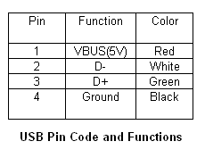
In recent years, the use of USB or Universal Serial Bus as a reliable communications interface in plenty of electronic devices have increased due to its increased speed, size and flexibility. It fundamentally consists of terminals VBUS(+5V supply), GROUND, D+ and D-. As plenty of of the devices run on rechargeable battery, it is now the trend to design the charging circuit that makes use of the power supply from the USB port to charge the rechargeable battery. This feature will make the devices more convenient to the users as the devices will get their power from the bus and requires no outside plug or cables.

USB Bus Powered Functions
Theres fundamentally three classes of USB functions on power that can be derived from the port.
High-Power Bus The high power bus powered functions derived all its power from the VBUS and cannt draw over 100mA until its been configured. One time configured, it can draw up to five unit loads(500mA) by requesting it in its descriptor. At full load, it must be able to work between the VBUS voltage of four.75V and five.25V.
Low-Power Bus The low power bus powered functions derived all its power from the VBUS and must not draw over one unit load (100mA) according to the USB standard. It must even be able to work between the VBUS voltage of four.40V and five.25V.
Self-Power Self power functions can draw up to 100mA from the VBUS and the rest from its outside source. This is the most simplest to design.

USB Port Powered Battery Charger
This application circuit makes use of the MCP73853/MCP73855 linear charge management controllers for cost sensitive applications. They are specially designed for USB applications and adhere to all the USB specifications governing the USB power bus. The circuit below makes use of the MCP73855 to design a USB powered Lithium Ion/Lithium Polymer battery charger by deriving the power from the USB port.
