circuit is designed by using another method. Using this circuit you can
toggle any electrical appliance between ON and OFF states by using
your TV remote. The only requirement is that your TV remote should be
operating in the 38 KHz.
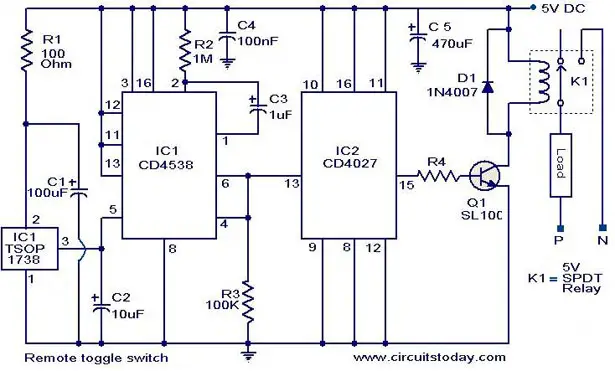
The IC1 (TSOP 1738)
is used to receive the infrared signals from the remote. When no IR
signal from remote is falling on IC1, its output will be high. When the
IR signal from the remote falls on the IC1, its output goes low. This
triggers the IC2 which is wired as a monostable multivibrator.The
output of the IC2 (pin6) goes high for a time of 1S (set by the values
of R2 and C3.This triggers the flip flop (IC2) and its Q output (pin
15) goes high. This switches on the transistor, which activates the
relay and the appliance connected via relay is switched ON. For the
next press of remote the IC1 will be again triggered which in turn
makes the IC2 to toggle its output to low state. The load will be
switched OFF. This cycle continues for each press of the remote. The
pin 6 and pin 4 of IC1 are shorted to avoid false triggering.The diode
D1 can be used as a freewheeling diode.
Circuit diagram with Parts list.is used to receive the infrared signals from the remote. When no IR
signal from remote is falling on IC1, its output will be high. When the
IR signal from the remote falls on the IC1, its output goes low. This
triggers the IC2 which is wired as a monostable multivibrator.The
output of the IC2 (pin6) goes high for a time of 1S (set by the values
of R2 and C3.This triggers the flip flop (IC2) and its Q output (pin
15) goes high. This switches on the transistor, which activates the
relay and the appliance connected via relay is switched ON. For the
next press of remote the IC1 will be again triggered which in turn
makes the IC2 to toggle its output to low state. The load will be
switched OFF. This cycle continues for each press of the remote. The
pin 6 and pin 4 of IC1 are shorted to avoid false triggering.The diode
D1 can be used as a freewheeling diode.
Notes.
- Assemble the circuit on a good quality PCB or common board.
- The circuit can be powered from a 5V DC regulated power supply.
- The capacitors must be rated 15 V.
- The IC1&IC2 must be mounted on holders.
- The
current capacity of relay determines the load circuit can switch.Use a
high amperage(`10A or above) relay for driving large loads like
motor,heater etc.


