Showing posts with label using. Show all posts

Morning Alarm Circuit Diagram Using LDR

,


Description

          Circuit showing a morning alarm.Here we have used a switching transistor.When the sun rise up ldr is low resistance so the ldr is conduct and a positive volt coming to the base of the Q1 there for the transistor will switch.This time  the buzzer is ON . Adjust the preset control the intensity of light.Manually cut off the power.Are you interested please comment and join this site


Component Required

                Resistor  4.7k preset  , LDR

                Transistor   BC 548

                Buzzer


Source by : http://www.electronics-circuits.in/2012/01/morning-alarm.html


Read more →

Emergency Lamp using IC 555

,
Emergency Lamp using IC 555
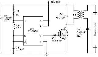
Emergency Lamp With 555 is one solution for lighting during power outages. With Emergency Lamp Series 555 uses a 12VDC voltage source that can be supplied from the 12V battery. Emergency Lamp 555 Series With these very simple and easy to make because all the components easily available in the market.

Emergency Lamp Series With this 555 can turn on the light 5W-10W. The circuit is built with an astable multivibrator with the IC 555 that is used to mendrive transformer through Q1. For more details can be viewed directly from the series Emergency Lamp With 555 follows.

schematic emergency lamp
Emergency Lamp Using TLC555

Working frequency range of 555 Emergency Lamp With this set of configurations R1, R2 and C2. T1 in series Emergency Lamp With 10V 500mA 555 is a transformer. Secondary part (0-10V) is connected to the Q1 to be given the signal from the multivibrator. Then the primary (0-220V) is connected to the lamp.
Read more →

Solar Charger Circuit Project Using Transistors

,
A very simple solar charger circuit project can be designed using few external electronic parts . This simple solar charger circuit is capable of handling charge currents of up to 1A. Alternate component values are given in the figure for lower current applications.

Solar Charger Circuit Project Using Transistors circuit diagram :


12V-SLA-chargher
The only adjustment is the voltage trip point when the current is shunted through the transistor and load resistor. This should be set with a fully charged battery. As the transistor and R3 have the entire panel’s output across them when the battery is fully charged, all of the current from the panel will be going through R3 and the Darlington transistor TIP112, so these must be well heat sunk. Adjust R1 for the trip point, usually 14.4 V – 15 V for a 12 V SLA or a 12 V Ni-Cd battery.

Source : http://www.ecircuitslab.com/2011/06/solar-charger-circuit-project-using.html
Read more →

Using Cell Phone Charger For Making a LED Tube Light

,

Using Cell Phone Charger For Making a LED Tube Light


A plug in wall lamp can be built at home by using a few white LEDs and by powering it through a cell phone charger. The power from cell phone charger is around 6 volts at 500 mA approximately. The power may be well suited and can be tried for powering white LED lights. The application includes some important types like a LED tube light, LED wall lamp, LED porch light, LED table lamp etc. to name a few.

A discarded, spare cell phone charger and a few inexpensive LEDs are all that you want you make a simple yet powerful LED tube light. The cell phone charger can also be used for making a porch light, a bed room wall light or a table lamp. Full circuit schematic is enclosed here in.
A nice little wall mounted cool lamp can be built using a few number of white LEDs and s discarded AC mobile charger adapter. The use of a cell phone charger makes the entire unit very compact and perfectly mountable on wall sockets.
Cell phone chargers are not new to us and nowadays we all seem to have a couple of in spare with us. This may be mainly due to the reason that whenever a new cell phone is procured a charger comes free within the package with the handset. This units are so long-lasting and rugged that most of the time chargers last more than the cell phones.
These spare cell phone chargers often lie idle and at some point of time we tend to dispose them off or simply discard them from our house. For a lay man these units may be a piece of junk, but a technical individual might make a complete gem out of it. Especially a person who may be an electronic hobbyist will very well know how valuable a cell phone charger can be even when it’s not being used for its actual intended purpose.
What are Cell Phone Chargers and How do they Function
We all have seen a cell phone charger working or rather being used for charging cell phones. Therefore we definitely know that it’s something to do with the supplying of some sort of power output.
That’s correct, these are actually a form of AC to DC adapters, however they are incredibly efficient as compared to an ordinary adapter which may employ a transformer for the required conversions.
Cell phone chargers are able to provide a nice six volts at a massive 800 mA of current. That’s quite big considering the size and the weight of these units.
Basically a cell phone charger is a high-grade SMPS power supply at the above rated level. Fortunately a white LED also works at potentials which quite matches with the above specs.
This prompted me to think of using a spare cell phone charger to be used as a plug-in type wall lamp. Mind you one charger can provide enough power to support at least 30 odd numbers of high power high-efficiency white LEDs. It simply means that the lights can be used as a compact LED tube light which can comfortably replace a common CFL light and generate light quite as good.
At no loads, a cell phone charger may provide outputs up to 10 volts, which can easily power a couple of LEDs in series. The series will consume a minimum of 20 mA, however since the charger can supply a good 500 ma plus current we can add 15 more such series in parallel, making the total accommodation close to 30 or more LEDs.
Parts Required
You will require the following parts for constructing the proposed project:
Series Resistors - All 68 Ohms, 1/4 Watt
An ordinary spare cell phone charger – 1no.
White LEDs – 30 nos. for making a small tube light or 10 LEDs for making a wall mounted bedroom lamp etc. (see text)
PCB – General purpose type or as per the project specifications.
Construction Clues
Constructing this LED wall lamp is not difficult as it only requires the LEDs to be fixed in rows and columns correctly as shown in the diagram. You may use the power from the cell phone to light any number if LEDs depending upon the requirement.
For example if you want to make a porch light for illuminating your house veranda, then probably you would need to assemble not more than 6 LEDs.
For making a cool bedroom room lamp a single LED would suffice, instead of sitting in complete darkness, this light may be used or switched ON while watching TVs or videos.
For making a table lamp for reading purposes, a group of 10 LEDs would provide enough light for the purpose. 

And as discussed above, a descent LED tube light can also be built by assembling some 30 + LEDs in conjunction with a cell phone charger power supply. 
For all the above applications, the basic mode of soldering and fixing the LEDs remains the same. Fix and solder a series of two LEDs with a series current limiting resister and now go on repeating this series as many times as you want, depending upon the type of lamp you are trying to build. Once you finish assembling this layout, you may go joining all the free ends of the resistors which becomes one of the supply terminals, similarly join all the remaining free ends of the LEDs, which becomes the other supply terminal of the unit. These supply inputs now just needs to be connected with the cell phone charger supply.
The LEDs should immediately come ON and produce illumination just as desired by you.
The assembly now needs to be housed appropriately inside a suitable plastic enclosure as per individual specification and liking.
Read more →

using IRF150 build a MCU system Controller 12V DC Motor Speed and Direction circuit

,
using IRF150 build a MCU system Controller 12V DC Motor Speed and Direction circuit
This
be power motor controller 12V circuit. with a signal MCU Control be
high class voltage , about 3V. It can motor control turn advance or
walk go backwards all right. By use power mosfet number IRF150 use
apply to 100W small stump size hills. The relay 12V 2 contract , for
change electronic pole gives motor. By feed a signal Reverse Rotation
change a B pins of 2N3904 give it works to give the electric current to
the coil relay. This circuit uses voltage 12V at current about 10A.
The C1-4700uF help increase efficiency of the circuit while , feed the
fire gives motor during first. The D2 use protect the electric
current pulls sharply from motor harm with mosfet Q1-IRF150 get.
Other detail in the circuit.
Read more →

Audio Indicator Circuit Diagram Using LM741

,

This circuit can be used to remotely monitor a loudspeaker, alarm, or audio source for presence of an audio waveform. It can also be directly connected across loudspeaker terminals used as a peak indicator. If you need to monitor some audio signal at a location that is either soundproof are too far away to actually hear the signal then you can use a circuit similar to this one.

Circuit Diagram:

Audio Indicator Circuit Diagram Using LM741 Audio Indicator Circuit Diagram Using LM741

A remote indication that the audio source is active is provided visually, here in the form of a LED. Referring to the above circuit, the 10k preset is a level control which should be adjusted so that when the source ( audio signal or alarm ) is producing the desired amount of noise, the LED lights. The input stage is an inverting x100 amplifier made with a 741 op-amp.

Author: Andy Collinson

Read more →

LM339 Using for LED VU Meter

,
This circuit in below uses two quad voltage comparator using IC LM339 to illuminate a series of 8 LEDs indicating volume level. Each of the 8 comparators is biased at increasing voltages set by the voltage divider so that the lower right LED comes on first when the input is about 400 mili volts or about 22 mili watt peaks in an 8 ohm system.


The divider voltages are set so that each LED represents about twice the power level as the one before so the scale extends from 22 mili watts to about 2.5 watts when all LEDs are lit. The sensitivity can be decreased with the input control to read higher levels. I have not built or tested this circuit, so please let me know if you have problems getting it working. This is the power levels should be as follows:
· 1 LED = 22mW
· 2 LEDs = 42mW
· 3 LEDs = 90mW
· 4 LEDs = 175mW
· 5 LEDs = 320mW
· 6 LEDs = 650mW
· 7 LEDs = 1.2 Watts
· 8 LEDs = 2.5 watts

Read more →

How to Make a Versatile Variable Voltage and Variable Current Power Supply Circuit Using Transistor 2N3055

,

 A power supply that does not include the features of a variable voltage and current control can by no means be considered truly versatile. A workbench power supply circuit explained in this article is not only specified with a continuously variable voltage control but is also equipped with the feature of overload or continuously variable current control.


A keen look at the circuit design reveals that it’s actually only an ordinary stabilized power supply circuit, however it yet still provides you with the proposed features very efficiently.
The voltage variations are made by using the preset P2, through a feedback configuration employing the components D1, R7, T2 and P2.
The inclusion of D1 makes it sure that the voltage can be lowered right down to 0.6 volts, which happens to be the forward voltage drop of the diode.
If any other specific minimum value is required then the diode can be replaced by zener diode having the required specified value.
Therefore in our circuit, the transformer being a 0 – 40 V, the output becomes variable right from 0.6 to 40 volts maximum, that’s very handy indeed.
For implementing the current control feature, T3 along with P1, R5 and R4 are involved.
The value of R4 is specifically becomes responsible for defining the maximum allowable output current.
P1 is set to choose the maximum range within the value that’s marked or identified by the resistor R4.

Parts List
R1 = 1K,
R2 = 120 Ohms,
R3 = 330 Ohms,
R4 = to be calculated using Ohms law.
R5 = 1K5,
R6 = 5K6,
R7 = 56 Ohms,
R8 = 2K2,
T1 = 2N3055,
T2, T3 = BC547B,
D1 = 1N4007,
D2, D3, D4, D5 = 1N5402,
C1, C2 = 1000uF/50V,
Tr1 = 0 – 40 Volts, 3 Amp

Read more →

Garage Door Closing Circuit Just using Relays

,
Because I’m old school, I wanted to build a Garage Door Closing circuit without relying on integrated configurations (555 timer etc) to keep it simplistic. The circuit closes the garage door after two minutes with C3 and four minutes with the addition of C2. The timer relay is surprisingly accurate (+/- five seconds). Another feature is to ensure that the garage door actually did close, such as if it’s stopped mid-operation by the user.


Garage Door Closing Circuit Just using Relays

Description:

S3 (magnetic N.C.) is located at the garage door and activates the circuit when the garage door opens.
RL1 is the reset timer. It’s maintained in the “on” position for two minutes by C3 while the trigger capacitor, C4, is charged. RL2 is the conduit, directing C4 to either RL3 or R1 to ground when off. Purpose of R1 is to prevent arching across contacts and a fast discharge. RL3’s contacts are connected to the Garage Door’s Momentary Switch and is sustained “on”  for a half second by C5.

When C3 discharges to the cutoff voltage of RL1, it turns off and resets. C4 charges C5, which turns on RL3 and initiates the garage door. Because C4 does not have the time to fully discharge, it should be at least three times the value of C5. If it does not close, RL1 in countdown mode will reset and open the door. When it resets again, the door will close.

Turning off the circuit, C1 maintains RL1 “on” slightly longer to ensure that RL2 is set to discharge C4 to R1. If this is not done and C4 is not discharged, the garage door will not open until it discharges naturally and falls below the trigger voltage for RL3.  The circuit would be useless for several days.

Garage Door Closing Circuit Just using Relays

Notes:
  • Time delay of RL1 after reset drops 15 seconds because of the short charge time.
  • To boost RL3 to a one-second delay, increase C5 to 1000uF.
  • D2, D3, and D4 isolate the crucial sections of the circuit.
  • Relays do not turn off at the same rate. I conducted a test by tripping the circuit on and off at a high rate and discovered the possibility of C4 turning on RL3. The addition of C1 solved this.
Author: Roland Segers email@:speedmail-at-gmail.com
Read more →